

Demonstration of an intense lithium beam for forward-directed pulsed neutron generation
Off-line time-of-flight (TOF) laser plasma analysis
The laser irradiation conditions replicated the ion-beam production experiments before the acceleration demonstration. The laser was a tabletop nanosecond Nd:YAG system employed at a laser power density of 1012 W/cm2 at a fundamental wavelength of 1064 nm, spot energy of 800 mJ, and 6 ns per pulse duration. The spot size on the target was estimated to be 100 μm in diameter. Since metallic lithium (Alfa Aesar, 99.9% purity) is sufficiently soft, the precisely cut material was pressed into the mold. The dimensions of the foil were 25 mm × 25 mm with a thickness of 0.6 mm. When the laser was irradiated, crater-like damage occurred on the target surface, so the target was moved by a motorized stage to provide a fresh part of the target surface for each laser shot. To avoid recombination due to residual gas, the pressure in the chamber was kept below the 10–4 Pa range.
The initial laser plasma has a small volume since the laser spot size was 100 μm and within 6 ns from its creation. It can be assumed that the volume is a pinpoint and then expands. If we put a detector at a certain distance xm from the target surface, the signal obtained follows the relations below for the ion current I, the arrival time of the ions t, and the pulse width τ.
$$ I propto 1/x^{3} $$
(1)
The generated plasmas were examined by TOF through the FC and energy ion analyzer (EIA) located 2.4 m and 3.85 m away from the laser target. The FC had a suppressor mesh biased at -5 kV to prevent electrons. The EIA had a 90-degree electrostatic deflector, which consists of two coaxial metal cylinder electrodes, with the same voltage but with opposing polarity, the outer positive and the inner negative. The expanding plasma was guided to the deflector behind a slit and bent by the electric field across the cylinders. An ion that satisfies the relation E/z = eKU is detected by the secondary electron multiplier (SEM) (Hamamatsu R2362), where E, z, e, K, and U are the energy of the ion, the charge state, the charge of the electron, the EIA geometry factor and the potential difference between the electrodes, respectively. When the voltage across the deflector was varied, the energy and charge-state distribution of the ions in the plasma was obtained. The scanning voltage, U/2, of the EIA ranges from 0.2 V to 800 V, corresponding to ion energies of 4 eV to 16 keV per charge state.
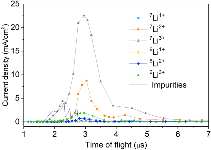
The analyzed ion charge state distribution with the laser irradiation condition described in the section “Generation of fully stripped lithium beam” is shown in Fig. 8.
figure 8
Analyzed ion charge state distribution. This is a temporal profile of ion current density analyzed by an EIA and scaled at 1 m away from a lithium foil using Eq. (1) and (2). The laser irradiation condition described in the section “Generation of fully stripped lithium beam” was used. By integrating each current density, the fractions of ions in the plasma shown in Fig. 3 were calculated.
ion source
A laser ion source can provide multi-milliampere class intense ion beams with high charge states. However, it has not been used commonly since the beam delivery was very difficult due to space charge repulsion force. In the conventional scheme, an ion beam is extracted from the plasma and transported to the first stage accelerator through a beamline, which has some focusing magnets to shape the ion beam to match the acceptance of the accelerator. In the beamline, the space charge force non-linearly diverges the beam, especially in the low-velocity region, and serious beam losses are observed. To overcome this issue in the design of medical carbon accelerators, a new beam delivery scheme has been proposed, ie, the DPIS41. We have applied this technique to accelerate the intense lithium-ion beam for the new neutron source.
The space where the plasma was generated and expanded was surrounded by a metal container as seen in Fig. 4. The enclosed space was extended to the entrance of the RFQ resonator, including the volume inside the solenoid coil. A voltage of 52 kV was applied to the container. In the RFQ resonator, the ions were extracted by the potential through a 6 mm diameter aperture, because the RFQ is grounded. The non-linear repulsive forces at the beamline can be eliminated since ions are delivered with a plasma state. In addition, as mentioned above, we applied a solenoid field combined with the DPIS to control and enhance the ion density at the extraction orifice.
Design of RFQ linear accelerator
The RFQ linac is composed of a cylindrical vacuum chamber as shown in Fig. 9a. Inside of it, four oxygen-free copper rods are placed with quadrupole symmetry around a beam axis (Fig. 9b). The 4 rods and the chamber form a resonant RF circuit. The induced RF field produces a time-varying voltage on the rods. Ions injected around the axis in the longitudinal direction are confined transversely by the quadrupole field. Meanwhile, the tips of the rods are modulated to generate an axial electric field. The axial field divides the injected continuous beam into a series of beam pulses, called beam bunches. Each bunch is contained in a certain time duration within one RF period (10 ns). The adjacent bunches are spaced according to the RF period. In the RFQ linac, the 2 μs beam from the laser ion source is transformed into a train of 200 beam bunches. The bunches are then accelerated to the designed energy.
figure 9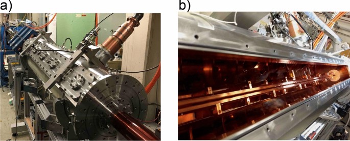
RFQ linac accelerator. (a) (left) The outside of the RFQ linac chamber. (b) (right) The 4-rod electrodes in the chamber.
The main design parameters for the RFQ linac are the rod voltage, the resonant frequency, the beam bore radius, and the modulation of the electrodes. The rod voltage, ± 29 kV, was selected to have an electric field lower than a threshold for electrical breakdown. With a lower resonant frequency, the transverse focusing force is larger, while the averaged acceleration field is smaller. A larger bore radius can accept a larger beam size and hence a larger beam current due to smaller space charge repulsion force. On the other hand, a larger bore radius requires larger RF power to energize the RFQ linac. In addition, it is limited from the field quality requirement. From these balances, the resonant frequency (100 MHz) and the bore radius (4.5 mm) were selected for the high current beam acceleration. The modulation was chosen to make beam bunches with small losses and maximize the acceleration efficiency. The design is iteratively optimized and a RFQ linac design was obtained that accelerates 40 mA of 7Li3+ ions from 22 to 204 keV/n in 2 m. The RF power was 77 kW, measured during the experiment.
Beam analyzer
An RFQ linac can accelerate ions that have a certain range of Q/A. Therefore, isotopes and other species must be taken into account to analyze beams transported to the end of the linac. In addition, the desired ions that are partially accelerated but dropped from the acceleration condition in the middle of the accelerator can still satisfy the transverse confinement and can be delivered to the end. The undesired beams other than design particles of 7Li3+ are called impurities. In our experiment, the main concerns about impurities are 14N6+ and 16O7+ because lithium metal foil can react with oxygen and nitrogen in the air. These ions have a Q/A that can be accelerated together with 7Li3+. We used a dipole magnet to separate beams of different Q/A to analyze beams after the RFQ linac.
The beamline after the RFQ linac was designed to transport fully accelerated 7Li3+ beams toward the FC after the dipole magnet. An electrode biased at − 400 V was used to suppress secondary electrons from the cup to accurately measure the ion beam current. With these optics, the ion trajectories were separated in the dipole and focused on different positions depending on the Q/A. The beam at the focal position has a certain width due to several factors, such as momentum spread and space charge repulsion force. Only when the distance between focal positions of two ion species is larger than the beam width, the species can be separated. To achieve as much resolution as possible, horizontal slits were installed near the waist of the beam, where the beams are nearly focused. There was a scintillator screen (CsI (Tl) from Saint-Gobain, 40 mm × 40 mm × 3 mm) between the slits and the FC. The scintillator was used to determine the minimum slit size for design particles to just pass through to achieve the best resolution, and to demonstrate that reasonable beam size of the high current heavy ion beam can be realized. The beam image on the scintillator was taken by a CCD camera through a vacuum window. The exposure time window was adjusted to cover the entire pulse width of the beam.
Comments are closed.